
Description
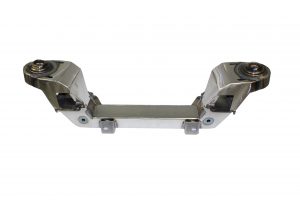
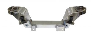
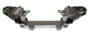
IF-4954CP-C Mustang II IFS for 1949-1954 Chevy with small block Chevy motor mount kit. Our famous Bolt-On Pinto Mustang II for 1949-1954 Chevy Car.
Safety Thru Engineering.
Handmade in the USA.
Exclusive adjustment system.
Interlocking design.
Superior strength.
Easy and accurate installation.
Correct geometry.
This custom-made bolt-on IFS kit is based on the Pinto /Mustang II independent front suspension system. Adding this kit to your ride eliminates bump steer and other unpleasant surprises resulting in a safe and enjoyable ride. The IFS cross member itself lowers your car about 2-4 inches when compared to stock, and with the adjustable upper coil spring pods there is about 2 1/2″ of additional adjustment possible to further fine tune your setup, providing the best method available to get the correct height geometry. The interlocking tabs between upper pods and lower cross member prevent movement.
Safety thru Engineering: This fully bolt-on IFS for 1949-1954 Chevy uses Pinto-Mustang II based suspension components. Using our 50+ years of expertise and experience, we have engineered this system to provide your classic 49-54 Chevy with a suspension that is far superior to that of the original Mustang II in safety, strength, handling and performance.
Interlocking design: The main bolt-on IFS for 1949-1954 Chevy cradles the frame for strength far superior to the commonly found weld-on cross members. Chevy frames are too thin to weld on safely and very frequently crack near the weld.
Adjustment System: Our exclusive ride-height adjustment system enables about 2 1/2″ of adjustable height at the coil spring pods, providing the best method for correct ride height geometry or to fine-tune your 1949-1954 Chevy. Note: The adjustment system provides a quick and easy way to correct the driving geometry of your ride. The cross member itself will lower your ride 2-4 inches from stock. It is important to keep the lower A-arms level. Our adjustment system allows you to set up the suspension correctly and then adjust as needed as your Chevy settles.
Easy and accurate installation: Build using the highest quality standards, our independent front suspension is easy to install. The unique bolt-on system can be mounted safely and securely on your 1949-1954 Chevy, and with the included instructions, installation of the cross member on your 1949-1954 Chevy is just a matter of following a few steps. The super-accurate fixtures we use when building your cross member ensure a perfect fit.
Recommended additional parts for your 1949-1954 Chevy Street Rod: Complete hub-to-hub component package, IF-7480TWM, when combined with this crossmember builds a complete front end. Kit includes new custom made upper and full lower control arms, spindles with nuts, caliper bracket kit, 11″ rotors, calipers with pads and pins, coil springs, manual rack and pinion, rack bushings, tie rod ends and shocks. The full lower control arms eliminate the need for support rods.
To fine-tune the ride height adjustment system on the IFS for 1949-1954 Chevy easily, consider our custom IFS wrench. Set-up rods that temporarily replace the shocks and springs for an easy way to set the correct ride height during your 1949-1954 Chevy build. For use with a small block engine, we recommend using 325lb coil springs, but others are available as well. For use with the Chassis Engineering IF-4954CP
Chassis Engineering Installation Instructions for IF-4954CP Mustang II IFS for 1949-1954 Chevy
1. Unbolt and remove original front cross member. Straighten the frame lips, if needed, where new cross member will sit. Remove any brackets and/or rivet heads that might interfere with fitting.
2. Clamp new lower cross member in place using the four 3/8″ holes that match the original cross member holes, Clamp cross member in place.
3. Place coil spring pods over frame and line up with lower cross member, Pods will fit only one way (taller side to the front). Check for clearances between frame and new parts. Correct any interference problems found.
4. Drill all vertical holes possible through frame lips using the cross member as a drill guide. Mark any remaining holes. Remove cross member and drill left-over holes. Note, the left inside rear hole will not have enough lip due to a factory cut-out. If possible, welding an extension to the frame there might be a good thing, but it can also be used as-is. The clamping action is sufficient.
5. Drill side holes (8 total) through coil spring pods and new cross member. Install bolts. The cross member, frame and pods should now be firmly attached to each other.
6. Install components from 1974-1980 Pinto or 1974-1978 Mustang II to complete installation (except lower control arm and struts). Manual steering is recommended. Installation must use one piece for lower control arms. These are available through us (Chassis Engineering) as well as other suppliers. See Ford or front-end manuals for installation instructions covering A-Arm, Spring, Shocks and line-up specs. Cut your coil to 12″ height (or order our coil springs, which are the correct size).
7. Our Chassis Engineering Springs are available in 25lb increments.
8. To adjust height, first take off all weight off of the springs. This means jacking the front wheels off the ground and possibly unhooking the shocks. Warning: to prevent injury,, make sure yo use jack stands to support the car at all times you may be working under it. Loosen 1/4″ locking set screw, and turn height adjuster to new position, The adjustment can be used to lower or raise the car, but is intended to compensate for different springs. For correct geometry, the lower A-arm should be parallel to the ground. Line up groove in threads and re-tighten locking set screw.
9. The final step, after height adjustment is to have the front end aligned to Pinto specs. Important: Steering U-Joint Fitting
10. We recommend using a Borgeson steering U-Joint. However, don’t use the locking nut and Allen screw that come with it, but instead use a Patch & Lock (self-locking) set screw (5/16″ x 18 x 3/8″). This will preclude any chance of the lock nut catching on the cross member. The nut will not catch under normal driving conditions as is. Again, changing to a self-locking Allen screw will prevent it from EVER catching under severe emergency situations, such as hitting a curb or bouncing through a ditch.
![]() WARNING: This product can expose you to chemicals including nickel and urethane, which are known to the State of California to cause cancer and birth defects or other reproductive harm. For more information go to www.P65Warnings.ca.gov.
WARNING: This product can expose you to chemicals including nickel and urethane, which are known to the State of California to cause cancer and birth defects or other reproductive harm. For more information go to www.P65Warnings.ca.gov.


Reviews
There are no reviews yet.