
Description
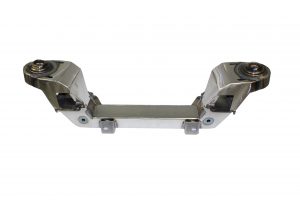
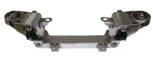
Our famous Bolt-On Pinto Mustang II Crossmember for 1948-1952 Ford truck, includes small block Chevy motor mounts.
Safety Thru Engineering.
Handmade in the USA.
Exclusive adjustment system.
Interlocking design.
Superior strength.
Easy and accurate installation.
Correct geometry.
This custom-made fully bolt-on crossmember kit is based on the Pinto-Mustang II independent front suspension system. Adding this kit to your ride eliminates bump steer and other unpleasant surprises resulting in a safe and enjoyable ride. The crossmember itself lowers your car about 2-4 inches when compared to stock, and with the adjustable upper coil spring pods there is about 2 1/2″ of additional adjustment possible to further fine tune your setup, providing the best method available to get the correct height geometry. Center support rods provide additional strength to the lower strut rod mount, and the interlocking tabs between upper pods and lower crossmember prevent movement.
Safety thru Engineering: This fully bolt-on crossmember uses Pinto-Mustang II based suspension components. Using our 50+ years of expertise and experience, we have engineered this system to provide your classic ride with a suspension that is far superior to that of the original Mustang II in safety, strength, handling and performance.
Interlocking design: The main bolt-on crossmember cradles the frame for superior strength. Adjustment System: Our exclusive ride height adjustment system enables about 2 1/2″ of adjustable height at the coil spring pods, providing the best method for correct ride height geometry or to fine-tune your ride. Note: The adjustment system provides a quick and easy way to correct the driving geometry of your ride. The crossmember itself will lower your ride 2-4 inches from stock. It is important to keep the lower A-arms level. Our adjustment system allows you to set up the suspension correctly and then adjust as needed as the car settles.
Easy and accurate installation: Build using the highest quality standards, our independent front suspension is easy to install. The unique bolt-on system can be mounted safely and securely, and with the included instructions, installation of the crossmember is just a matter of following a couple of steps. The super-accurate fixtures we use when building your crossmember ensure a perfect fit.
Recommended parts: Complete hub-to-hub component package, IF-7480TWP (power rack version) or IF-7480TWM (manual rack version), when combined with this crossmember, builds a complete front end. Kit includes new custom made upper and full lower control arms, spindles with nuts, caliper bracket kit, 11″ rotors, calipers with pads and pins, coil springs, manual rack and pinion, rack bushings, tie rod ends and shocks. The full lower control arms eliminate the need for support rods. Complete hub-to-hub component package, IF-7480HHP (power rack version) or IF-7480HHM (manual rack version), when combined with this crossmember builds a complete front end. Kit includes new custom made upper and lower control arms, strut rods with bushings, spindles with nuts, caliper bracket kit, 11″ rotors, calipers with pads and pins, coil springs, manual rack and pinion, rack bushings, tie rod ends and shocks.
To fine-tune our ride height adjustment system easily, consider our custom IFS wrench. Set-up rods that temporarily replace the shocks and springs for an easy way to set the correct ride height during the build. For use with a small block engine, we recommend using 325lb coil springs, but others are available as well.
Chassis Engineering Installation Instructions for IF-4852FPT Mustang II IFS for 1948-1952 Ford Truck
1: Remove the original front suspension. Straighten the edges and lips on the frame where the new cross member and support rods will be placed. Make sure the frame edges are a straight 90 degrees from the side of the frame. Remove any rivet heads that might interfere with proper fitting of the cross member. Grind these flush with the frame.
2: Bolt the new lower cross member to the bottom of the frame using the dimensions below: The steering mounts on the cross member point to the front. Measure from the center of the original front spring mount to the front of the new cross member.
3: Place the coil spring pods over the frame and line them up with the lower cross member. The pods will only fit one way, and the taller side needs to be on the front. Check for clearance between the frame and the new parts. Make the modifications needed to correct anything that will interfere with a proper fit. At this point, performing a wheel centering check is recommended. While there are normally no issues with this, it never hurts to check to make sure you don’t run into anything further into your build. Assemble the A-arms and spindle on one side, without a spring in place, and installing a wheel. Now look it over to make sure it is centered. While rare, if there is an issue with centering, the cross member can be moved slightly to correct this.
4: Now clamp the upper and lower pieces together in the location where it needs to be. Again, check and make sure nothing is causing any fitting issues. Drill the 8 holes per side, vertical holes first, and bolt it all together tightly. The cross member, the frame and the coil spring pods should now be firmly attached together.
5: Strut Rod Support Brackets Straighten the frame edges, where the strut rod support brackets will sit, to a straight 90 degrees angle. Put a bracket in place around the frame and insert a bolt in the center brace to the crossmember tube. Now fit the bracket to the frame and find the spot where it has the best fit. Do both sides, and compare the measurements. Average these to make the brackets on both sides the same. Now clamp them in place. Note: brackets will only fit the frame properly if the edges are properly straight.
6: Drill the holes underneath the frame first, making sure that the brackets sit flush with the outside frame. Then do the outside holes and bolt things together as you go.
7: The IF-4852FPT (this kit) comes with two rack extensions. These are needed to move the tie rod inner pivot outward. If these extensions are not used, you will likely run into steering issues. The kit is 2 inches wider than a stock Pinto one, and these spacers are critical to keep the geometry the same. Make sure that these extensions are locked to both the rack and the tie rod. There are multiple solutions for this, but we recommend drilling a 1/8″ hole drilled half-way through the extension and the original shaft, and a roll pin driven in to act as a lock. Note: The spacers/extensions included are for an original standard steering and pinion setup. If you are using power steering or have an aftermarket replacement rack installed, then contact us before ordering.
8: Install components from 1974-1978 Pinto or 1974-1978 Mustang II to complete installation. We recommend manual steering. Use Pinto struts, and not struts from Mustang II. Use a new strut bushing set. See Ford or front end manuals for installation instructions covering the A-arms, Strut Rods, Springs, Shocks and the line-up specs.
9: Coil springs needs to be cut to 12″ height. If you use our Chassis Engineering coil springs then they already are properly sized. We have springs available in 25lbs increments.
10: For safety, always use jack stands whenever you may be working underneath your ride. For height adjustment, start with taking off all the weight off of the springs. Jack the front wheels off of the ground and (possibly) unhooking the shocks. Loosen the 1/4″ locking set screw and turn the height adjuster to its new position. You can use this adjustment to raise or lower the car, however, it is intended to compensate for different springs. To make this adjustment a breeze, we have a custom IFS adjustment wrench (IF-0000W) For correct geometry, the lower A-arm should be parallel to the ground. Line-up groove in threads and re-tighten the locking set screw.
11: On a “fresh” car with a new IFS setup, after some good road miles, check the coil springs for proper setting. New springs settle after a while, so it is a good idea to check if adjustments are needed to make sure the lower control arms are parallel to the ground. When making the adjustment, remember to loosen (and re-tighten afterwards) the locking set screw. Adding a little anti-seize compound before turning down the spring adjuster doesn’t hurt either.
![]() WARNING: This product can expose you to chemicals including nickel and urethane, which are known to the State of California to cause cancer and birth defects or other reproductive harm. For more information go to www.P65Warnings.ca.gov.
WARNING: This product can expose you to chemicals including nickel and urethane, which are known to the State of California to cause cancer and birth defects or other reproductive harm. For more information go to www.P65Warnings.ca.gov.


Reviews
There are no reviews yet.